Baofengs seem like a good choice for inexpensive APRS etc. However I’ve always run into an issue which I’ve never found a solution for – the rig keys up, but doesn’t unkey again. Not much good.
I just came across this page, which claims to solve it. Summary: put a 2.2k resistor in series with the PTT line.
No explanation given as to why that fixes it. I will try this out…
You’ve likely heard of QO-100, or Es’hail 2. It’s the first geostationary satellite carring an amateur radio payload. Geostationary means it’s always in the same place in the sky, so no waving yagis about, and the amateur radio payload is a pair of transponders. One narrowband, which I’m targeting, and one wideband, which is good for DATV, but requires more kit and more TX power than I have.
The narrowband transponder is what’s known as a linear transponder. Like commercial TV satellites, a narrowband transponder receives a chunk of spectrum on one band, and re-transmits the entire chunk of spectrum on a different band. In this case, QO-100 receives 2400.050MHz to 2400.300MHz and retransmits the same block of spectrum at 10489.550MHz to 10489.800MHz, i.e. signals coming down from the satellite are shifted up by 8089.5MHz compared to the uplink.
QO-100 has clearly been designed to be straightforward for amateurs to work. Both the uplink and the downlink are in amateur bands, the uplink is adjacant to the 2.4GHz Wi-Fi / ISM band, so there is loads of gear floating around already for this, e.g. high gain antennas, and the downlink is right next to the frequencies used for commercial satellite TV, around 10-11GHz, meaning regular satellite TV dishes and LNBs can be used to receive the downlink on inexpensive receivers or general coverage scanners / amateur radio transceivers. More on equipment later…
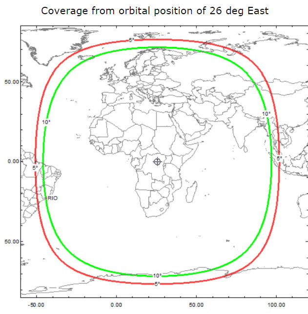
Being a geostationary satellite, it’s also very high. (Owing to orbital mechanics all geostationary satellites occupy the same altitude – 35,786 km above the equator.) This is around 3 earth diameters above the earth’s surface. There is no talk of any beam-forming on the QO-100 amateur transponder, so the footprint is basically all of the earth it can see:
View from QO-100, courtesy AMSAT UK
Footprint of QO-100, courtesy AMSAT UK
Strictly the title of this post is a lie – but only if you’re an EME buff! A QSO held via QO-100 does 72000km / 45000 miles. That’s 1.8 times around the Earth’s equator, and the speed of light delay, i.e. exclusing any digital latency, is around 0.25 seconds. A trip up to Es’hail 2 and back is roughly the same as a fifth of the way to the moon.
The traffic typically seen on QO-100 is a mixture of SSB – in the top half of the passband – and mixed digital modes / CW in the bottom half. SSB seems to be most popular, and despite the distance, a couple of watts into a reasonable antenna is more than enough to get in comfortably and reliably.
When I read about QO-100, I knew I had to get a setup together. So I did my research and started buying parts. Fundamentally, my setup is:
Receive: Octagon PLL LNB connected to an SDRPlay RSP1 connected to a laptop running SDR Console.
* NB this company pulled a fast one, jacking up the price of that antenna significantly just before the well known RadCom article landed on doormats. Not cool.
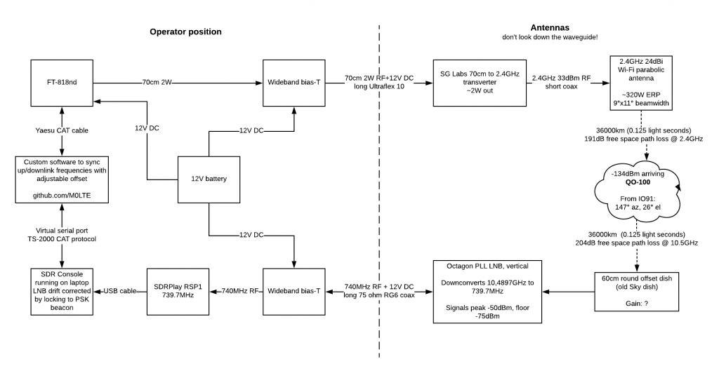
Here’s a block diagram showing things in more detail:
Block diagram of my QO-100 setup, with a few back of the envelope calculations, which should maybe come with a health warning!
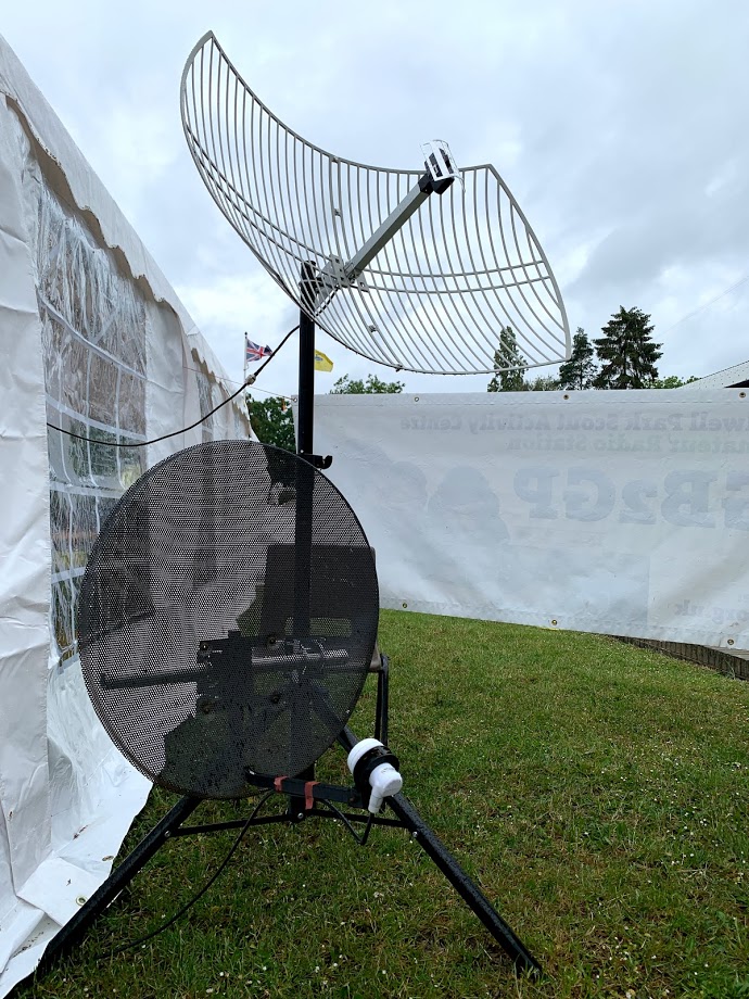
Here’s what my portable setup looks like:
The 2.4GHz grid antenna at the top for transmit, and the 60cm old Sky dish for 10GHz receive, on a cheap speaker stand
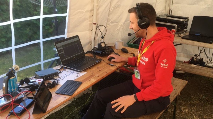
The FT-818nd, transverter, SDRPlay RSP1, laptop, and me!
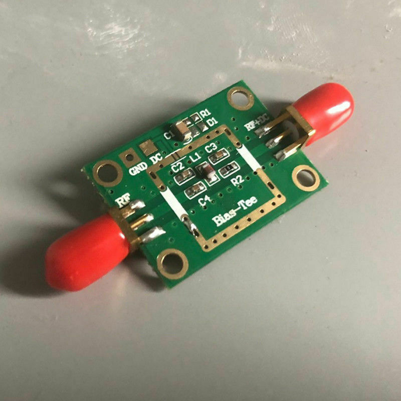
Both the transverter and the LNB need power. Both take power up the coax. This needs to be injected via a pair of bias Ts. A bias T can be used to either inject DC into the near end of a coax cable while keeping it out of a radio, or to extract DC from the far end of a coax cable to power something. The LNB would ordinarily be powered by a Sky TV box using an internal bias T, but in the absence of that, we have to provide one.
An inexpensive bias T from eBay. The red caps are dust covers and can be discarded. Underneath are SMA sockets. The solder on these connectors benefits from being beefed up for physical strength.
* the laptop and SDR can be swapped out with any receiver that can cover 739 – 740MHz upper side band.
Setup
Choose whether to start with Transmit or Receive.
Receive
Mount the receive dish to the tripod (or your house!). It doesn’t need to be high, just have a clear view of the southern sky (147 degrees from IO91) at 26-27 degrees elevation above the horizon from the UK. Obviously this will vary internationally.
Fit the LNB to the satellite dish arm, F connectors pointing downwards.
Terminate a length of RG6 satellite coax with F plugs and run it from the LNB to your operating position. The signals off the LNB are very strong (up to -45dBm), so length isn’t a problem.
Put an F to SMA adapter on the end of the RG6. Plug that into a bias-T – side marked DC+RF.
Feed 12V to the bias T.
Plug an SMA to SMA patch lead into the other side of the bias-T, marked RF. Plug the other end into your receiver / SDR.
The LNB is a 9750MHz downconverter when fed 12V DC. Centre the SDR waterfall on 739.5 to 739.8MHz, zoom out to approximately 0.5MHz span across the screen.
Download an app such as Satellite Pointer for iOS to get a rough first alignment. Plenty of other apps out there. If Es’hail 2 / QO-100 isn’t in the app, look for Es’hail 1, it’s in about the same place. Failing that, point it in roughly the same direction as your neighbours’ Sky dish.
Start zeroing in on the right location. Set yourself up so you can see your SDR waterfall at the same time as you can tweak the dish. Start with azimuth, then elevation. The face of an offset dish should be roughly vertical when pointing at QO-100 from the UK. Tiny adjustments are required. You will notice shadows on the waterfall – the strongest signal will be around 739.8MHz +/- inaccuracies in the LNB / SDR LOs. This is a beacon which is constantly on and is supposed to be the strongest signal on the satellite.
When you locate the beacon, click on it in SDR Console to get a signal strength reading. Then start alternating between adjusting azimuth and elevation until you can observe a difference of around 20dB between the noise floor and the beacon signal. When done, try adjusting the skew (rotation) of the LNB. This more closely aligns the vertical polarisation of the LNB with the tilt of the downlink, given the sat is off to the east relative to the UK. Obviously adjust for interational locations.
Compare yourself to the Goonhilly WebSDR (maybe I should have mentioned that earlier…) to check you have reasonable performance.
Transmit
Connect the RF end of another bias T to the FT-818nd using a PL259 or BNC to SMA male cable.
Connect 12V to the bias T.
Connect the DC+RF end of the bias T to the near end of the Ultraflex 10 coax using an SMA to N female pigtail
Connect the far end of the Ultraflex 10 coax to the IF input port of the transverter using an N female to SMA male pigtail
Connect the transverter’s antenna port to the dish using an N male to SMA male pigtail
If using a separate dish, mount it and point it at the satellite. Mine is a prime focus parabolic grid antenna so it looks like it’s pointing way higher than the round Sky dish. Aiming is much less critical – set the azimuth to the identical to the arm of the Sky dish, and the elevation using an inclinometer / spirit level app on a smartphone to 26 degrees above horizontal.
Operating
Operating on QO-100 is much like any other non-inverting linear transponder. Before you transmit, make sure you can see signals in the receive passband. An SDR waterfall display is highly recommended. You transmit using low power on 70cm using SSB into the transverter, the transverter converts that to 2.4GHz, and up it goes to the satellite. This comes back down at the 2.4GHz frequency plus 8089.5MHz, so you need to find yourself on the downlink, since that’s where anyone responding to you will be transmitting.
The frequency range to transmit voice SSB on is 432.2 to 432.3Mhz, corresponding to 2400.2 to 2400.3MHz on the uplink, and 10489.7 to 10489.8MHz on the downlink, which can be heard on the output of the LNB at 739.7 to 739.8MHz. Seems complicated but once you’re going it’s really not.
I wrote a little bit of software that syncs the VFO of my physical radio with the VFO of SDR Console. It’s a bit basic still, but is here anyway. Makes keeping your uplink and downlink syncronised, and fine tuning, pretty easy. Supports CLAR on the Yaesu radio too, which is pretty neat.
Frequency table Here are the frequencies of the signals at each of the stages through the whole setup. Each frequency is the lower edge of that section.
The LNB drifts significantly with temperature. To correct for this, you can modify the LNB, or more easily, you can correct for it in software. Setting up SDR Console for QO-100 is covered here.
Signal strength
If you transmit too loud a siren will sound on top of your downlinked signal. Back off the power if this happens. Do not transmit FM up to the satellite.
Results
To date I’ve worked from South Africa to Iceland, Brazil to Thailand all using 2W into my Wi-Fi dish using SSB, with good reports.
I’ve tried a little bit of FreeDV (narrowband digital voice for HF), decoding myself via the WebSDR on a second laptop, which worked surprisingly well even in the face of my basic equipment with no GPS-disciplined LO. This was a bit of a surprise.
I tried a bit of SSTV just for giggles. Nearly fell off my chair when someone responded. I had technical challenges with the receive audio so I never found out who it was. But again I was able to decode myself on the WebSDR on a second laptop. This mode seems very susceptible to timing mishaps due to drift.
The experience is like HF, but with some added challenges (resulting in learning opportunities), minus the uncertainty of propagation. This is my first foray into anything above 70cm, and it’s been great fun.
Now I have a working “reference” setup based largely on commercial parts, my plan is to experiment with different dishes, feed points etc so I have something known good to compare against. I also want to experiment further with digital voice, and try out maybe some 300 baud packet and maybe some weak signal PSK stuff.
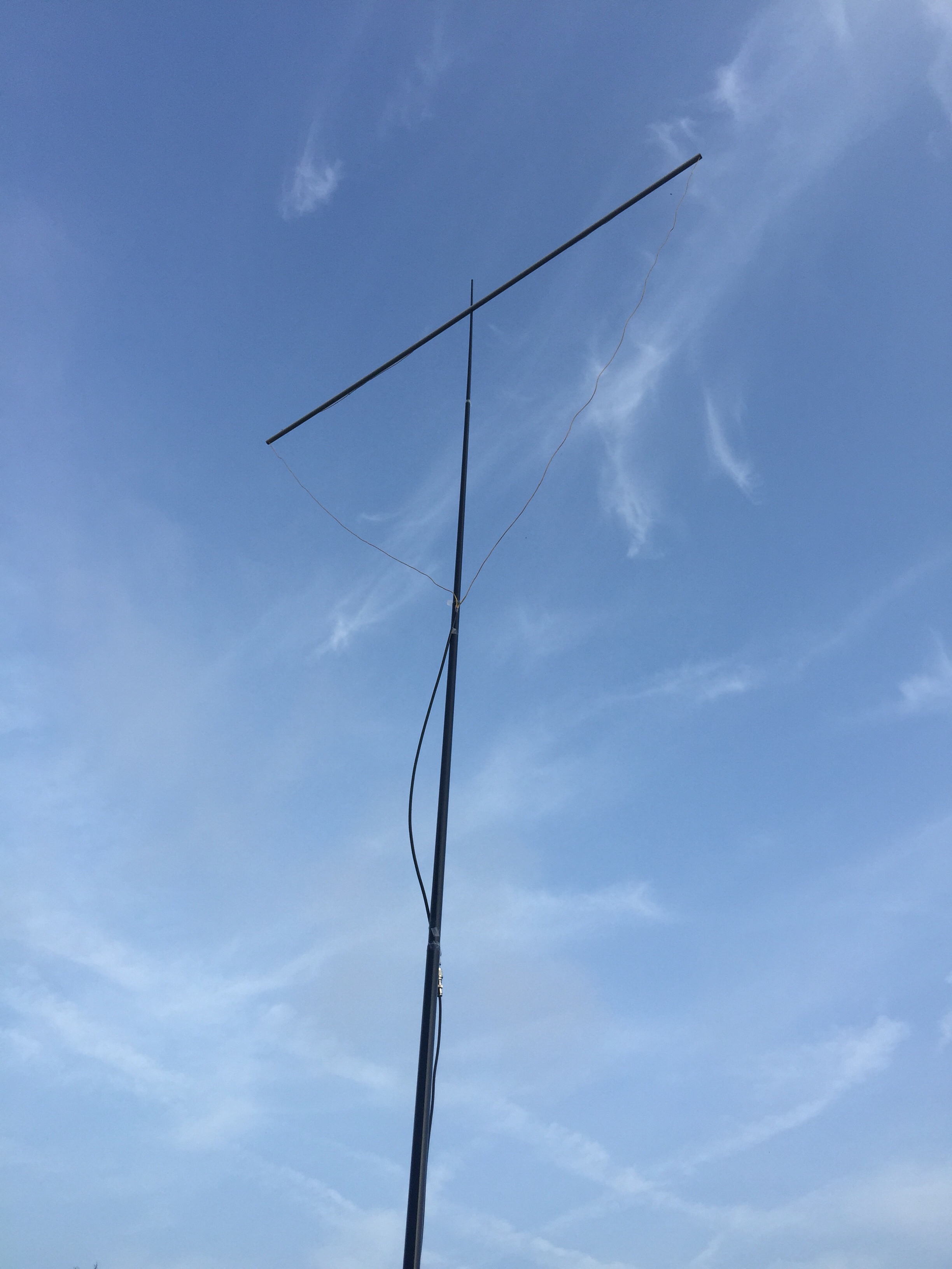
This week I put together a simple delta loop antenna for 6m. This is a simple, cheap, lightweight horizontally polarised somewhat-directional antenna. Fantastic for the sporadic E season which is going on right now – especially in a confined space where a beam isn’t practical.
It looks like this:
I made it out of 6m of hookup wire, some 75 ohm coax, 2m of plastic pipe, and a PL259 connector. All of which I found in the garage.
It is hung on a SOTABEAMS fibreglass pole, about 6m above ground level in my case. No guys, just strapped to the washing line with velcro.
Almost immediately after plugging it in, I decoded PV8DX in Brazil on FT8. That was exciting! Even if it was a fluke. Since then I have worked Italy on SSB, and Malta, Estonia, Spain, Italy, Sardinia on FT8. Right now I’m +8dB into Sardinia, so this thing gets out okay!
A quick test on a web SDR shows a 9dB difference between broadside and end-on, so it’s reasonably directional.
A word on matching. A delta loop has a nominal impedence of 100 ohms. To match to 50 ohm coax, this design uses a simple piece of 75 ohm coax as an impedence transformer. This works by taking advantage of the mismatch between 50 and 75 ohm coax. For 6m, a 99cm length is necessary. No other matching or choking seems to be required for this antenna, so it should be fairly low-loss.
The construction details:
Cut 105cm of 75 ohm coax. Strip 3cm off each end, leaving 99cm intact.
Cut 2x 3.1m lengths of wire. I used RS 356-713, obsolete, but any will do.
Join one length of wire to the shield of the coax, join the other length of wire to the centre conductor of the coax.
Drill a hole just wide enough for the wire at each end of the plastic pipe, through both walls. My two holes were 198.5cm apart from each other.
Feed each piece of wire through one of the drilled holes. Bring together, strip and twist together the two pieces of wire at the midpoint of the pipe.
Put a connector on the free end of the 99cm bit of coax.
Drill a hole through the plastic pipe around 8-10mm, enough to push the second-to-top section of the SOTABEAMS mast a reasonable way through it.
Connect your antenna to your coax, raise the mast, tune for SWR by chopping out short lengths of wire until the SWR is low at the desired centre frequency. I found perfect resonance (50 ohm resistive, 0 ohm reactive, 1.0:1 SWR) at 50.313MHz, the 6m FT8 frequency, with 598.5cm wire. This bit is much easier with an antenna analyser but can be done with a rig set to lowest power and an SWR meter.
Finalise and seal the connection between the two pieces of wire.
Finding the perfect length of wire for resonance will depend on the accuracy and quality of the 75 ohm section, and on the velocity factor of the antenna wire, which can vary. The maths predicts that resonance at 50.313MHz should be 5.963m of wire, so 5.985m (22mm difference) is damn close.
I quite fancy making 2m and 4m versions of this. The following table shows scaled measurements for 2m and 4m, based on this successful implementation for 6m.
You should be able to easily import this file into your compatible radio to avoid fiddling with manually programming the channels. Use of the channels rather than the VFO will guarantee you don’t operate out-of-band.
Since information on my old Yaesu FT-470 handheld is starting to become hard to come by, I thought I’d start a post where I put stuff I need to remember or often look up about it.
There won’t be much here to start with, but it might well grow over time.
Fed with 12V, the radio will manage 5.0W VHF and 5.0W UHF, according to the manual. The rig can be fed with anywhere from 5.5V to 15.0V.
The microphone is a 2-kilohm condenser.
Mirroring a post from 1991:
From thunder.mcrcim.mcgill.edu!snorkelwacker.mit.edu!bloom-beacon!micro-heart-of-gold.mit.edu!wupost!zaphod.mps.ohio-state.edu!mips!cs.uoregon.edu!ogicse!emory!wa4mei!ke4zv!gary Sun Sep 29 20:54:05 EDT 1991

In article <1991Sep27.033057.22510@agate.berkeley.edu> ajk@garnet.berkeley.edu (Adam Jacobs N2LAW) writes:
>
>1.  Does anyone have the exact wiring specifications for the Yaesu
>side of the cable to the TNC?  Is "where do I plug it in" a stupid
>question?  Presumably the MIC and EAR jacks, but how is the MIC jack
>configured -- if it's (as the manual specifies) a 2-conductor
>micro-mini phone jack, then what do I do with the PTT signal?  Or is
>there something else I should know?  I can wire the cable all right,
>but I have no appetite for blindly trying configurations on an
>expensive piece of equipment.  Do I have to open the unit up?

The FT470 is wired like an Icom. You connect the audio from the TNC
to the tip of the mike plug through a capacitor and connect the PTT
to the tip with a resistor. The Icoms and Yaesus use a "leaky ground"
to generate PTT. The problem with this approach is there is a tradeoff
between rapid PTT and audio level and response. Typical values are
.1 ufd and 2.2 k ohms. The RC time constant limits TR turnaround.

A better scheme is to use a tiny audio transformer sideways like so,


TNC PTT----------))))))))))))------------> radio tip (audio)
                 ============
TNC AF OUT-------))))))))))))----X--------> radio sleeve (gnd)
                                 |
TNC GND--------------------------|

You can rip a suitable transformer out of an old transistor radio or
buy one from Radio Shack.

>2.  Suppose I want to run the HT off a 12V external power supply.
>Where do I feed the power?  Not the battery terminals, I hope.  I
>would have expected a DC power jack somewhere on the unit, but again I
>don't see anything except a mysterious looking rubber plug-which-might-
>hide-a-jack-but-I'm-afraid-to-pull-it-and-look.  The manual, again,
>says nothing about this.

The 2 meter only model does have a power jack under the rubber plug, but
the 470 doesn't. There's a place on the board for one, but Yaesu recomends
that you use a PA-6 module instead. This is a module that mounts in place
of the battery and contains regulators for running the radio and charging
a battery connected to the bottom of the PA-6. This is a really nice
accessory and well worth the price.

>3.  Anything else (useful modifications, hints, caveats) I should know
>about the FT-470 (or PK-88?)

Just the standard remarks that you should carefully set the audio level
so you wind up with a 3 khz deviation for your tones. Don't exceed that
level or many units will have trouble decoding your packets. Make sure
you have the power saver on the 470 turned off when you run packet or
you'll miss the first part of every packet. This can drive you nuts
because everything seems to be working but nothing prints.

One last note. Use a separate antenna and use shielded cables on your
TNC. Otherwise the RFI and RF feedback will ruin your packet operation.

Gary KE4ZV
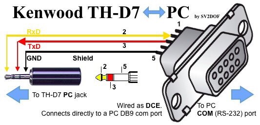
TNC TX audio -> 0.1uF cap -> 2.5mm tip
TNC PTT -> 2.2k resistor -> 2.5mm tip
TNC RX audio -> 3.5mm tip
TNC gnd -> 2.5mm / 3.5mm ring
or the transformer method, which I’ve never tried.
Headset / speaker mic wiring – unverified – need to tear apart a headset I have somewhere to check.
Mic + -> 2.5mm tip (presumably the cap isn’t required as in the TNC)
Mic – -> 2.5mm gnd
PTT will be 2.5mm tip -> 2.2k resistor -> switch -> 3.5mm tip
Headphones is just 3.5mm tip and 3.5mm gnd
Again, that is unverified.
Any speaker mic must be a design where the PTT switch is double poled, where the second pole interrupts the speaker connection, else audio feedback happens on TX.