Here’s my experience fitting a hupRF PAT 50 board to a Yaesu FT-840 HF transceiver
Remove the handle, and remove the two screws on each side.
Remove the case screw from the top edge of the rear.
Carefully lift off the lid and unplug the speaker cable. Set the lid aside.
Turn the radio upside-down, remove the feet and the six case screws.
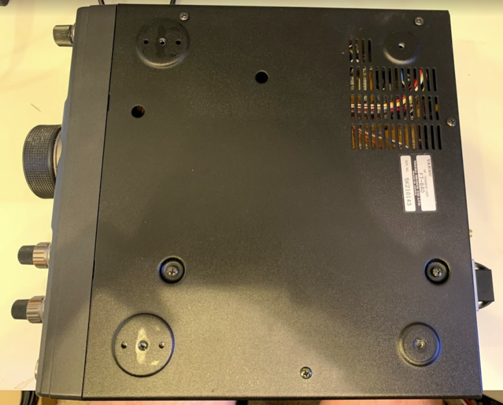
Carefully remove the bottom panel of the radio, lifting the rear edge first to avoid damaging the bottom of the front panel.
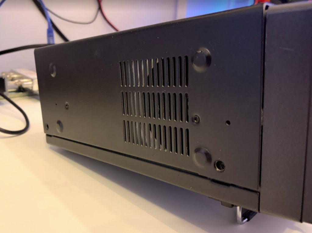
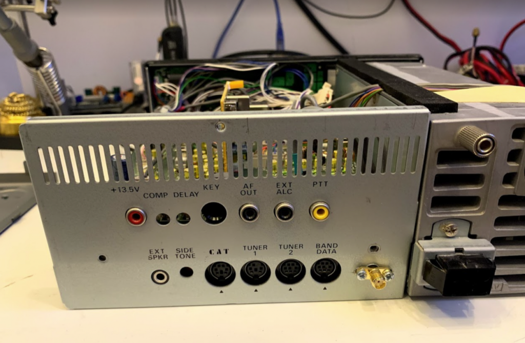
Remove the two screws from the connector panel on the back of the radio. Remove the panel, fit the SMA socket to a suitable location on that panel, and solder on some trailing coaxial cable. Set aside.
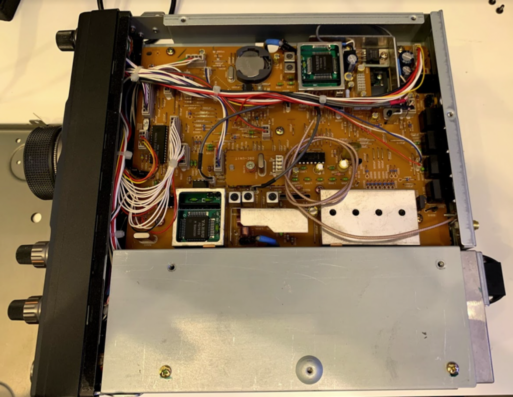
Turn the radio the right way up again, remove the six screws holding in the main PCB.
Snip the two cable ties at the front of the radio, one on the main wiring bundle and the other on the right hand side. Snip the other cable tie holding the speaker cable. Unplug the coax connector from the right hand side of the board (J1010).
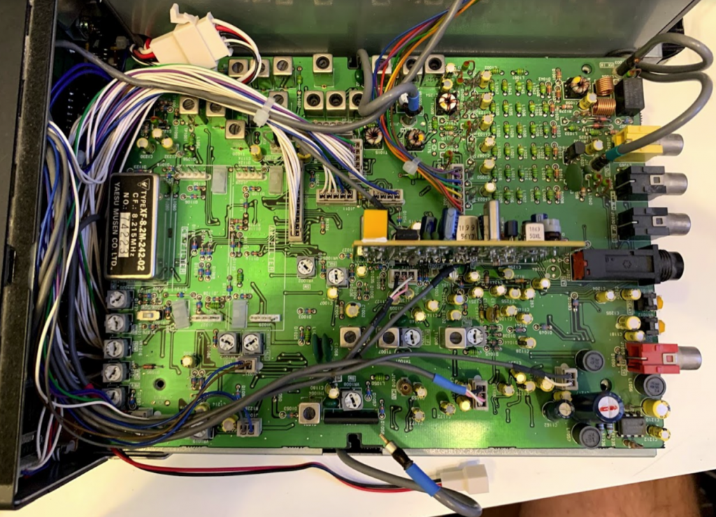
With the right hand side of the radio towards you, gently flip up the near edge of the PCB to expose the solder side, gently moving any remaining wires out of the way.
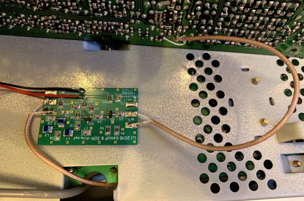
Attach the hupRF board to the metal case using double-sided tape.
Put the rear metal panel on the right hand side of the radio on the workbench, and thread the coax cable up through the bottom plate of tha radio, following the route of the existing coax cable that you disconnected earlier.
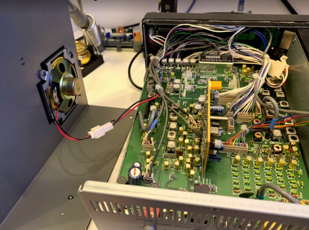
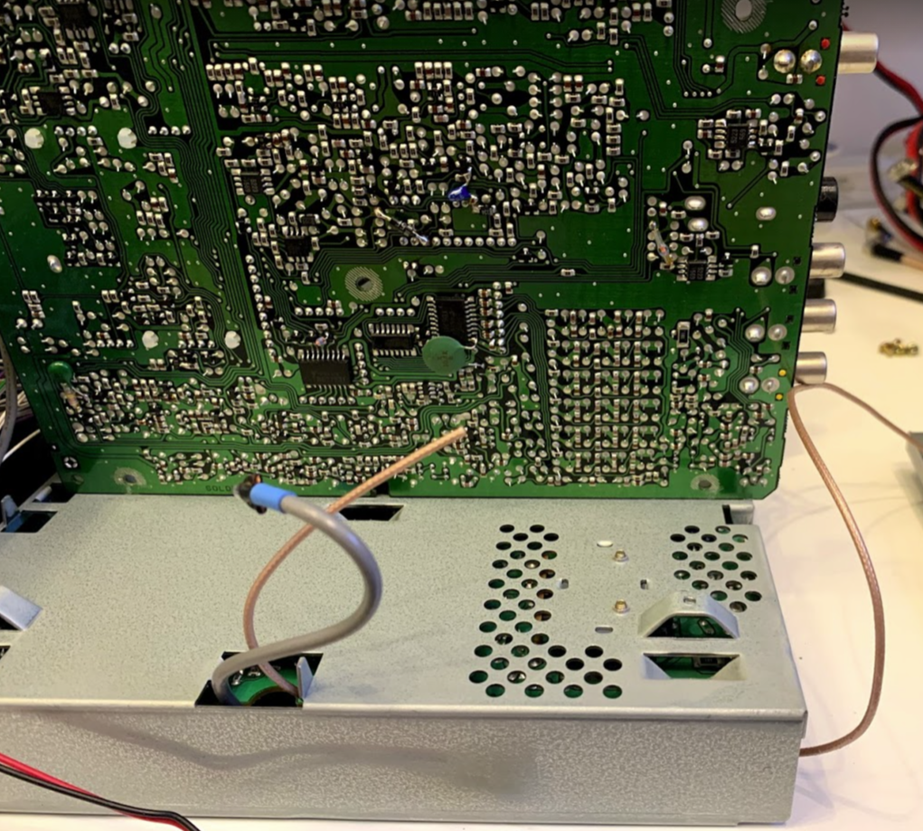
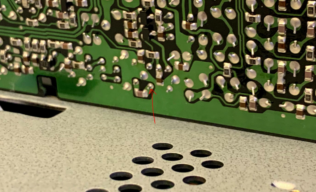
Turn on your soldering iron and prepare the ends of the coax cable. We will be connecting the ground side of the coax to the PCB ground, and the centre conductor of the coax to the point marked in the following photo:
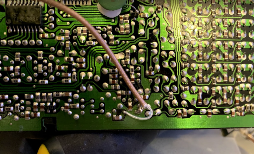
I went with this kind of arrangement:
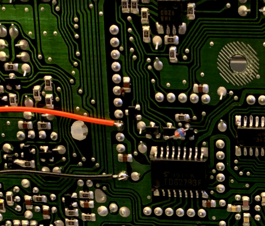
The PCB tap point should connect to the IN side of the hupRF board, and the coax socket on the back of the radio should connect to the OUT side of the hupRF board.
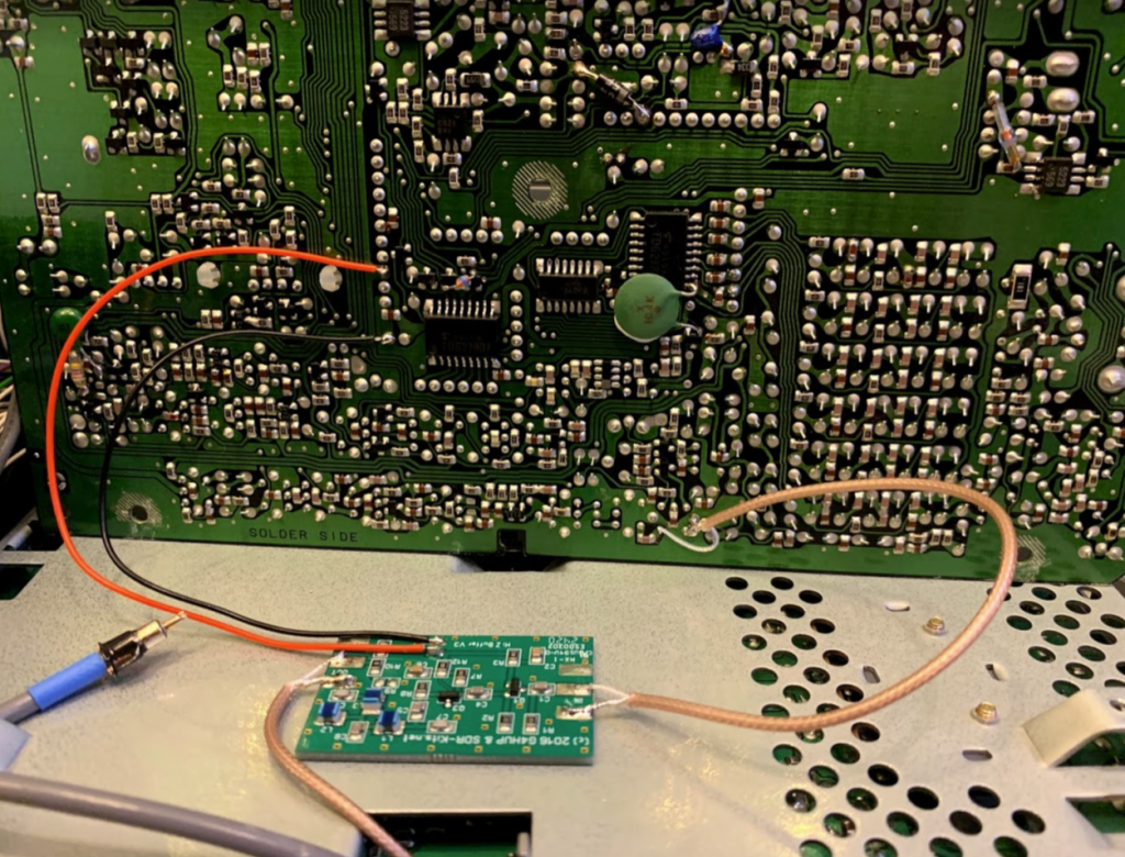
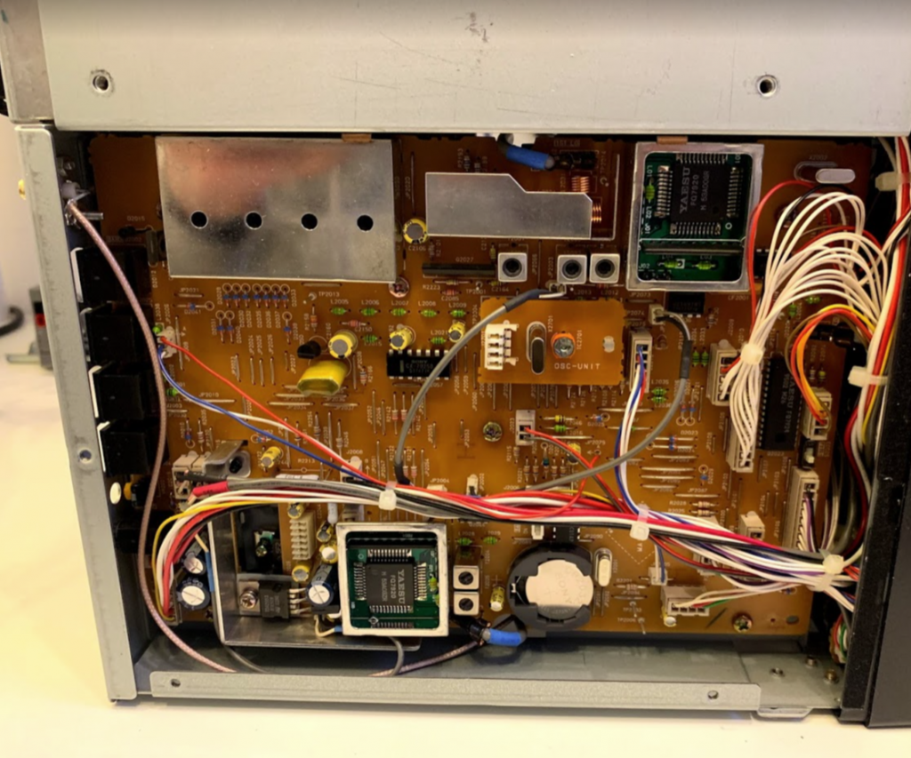
9V is picked up from pin 3 of the 11 pin socket, and ground is picked up from pin 1 of the same socket.
JP1 on the hupRF board is where the power goes to. The hupRF manual says not to connect the ground side of the tap input coax to ground, but I did anyway.
Don’t worry about the fact that there’s very nearly a DC short between the tap pin and rig ground – it was like that before you dived in! It does mean that it’s a little difficult to check your work with a multimeter though.
Gently flip the PCB the right way up, reconnect the disconnected internal coax cable, gently move any misplaced cables back into the right spot. Do up the central PCB screw.
Attach the rear panel, routing the new coax appropriately.
Power up the radio (taking suitable precautions given the lack of panels) and check for RX.
Assuming all is well, proceed to reassemply. Replace the three cable ties cut earlier, and replace the remaining four PCB screws.
Flip the radio upside-down and refit the base and the feet.
Flip the radio the right way up and refit the lid, not forgetting to reconnect the speaker cable. Do up the lid screws. The four countersunk screws go on the sides of the case.
Re-check the radio, and enjoy!
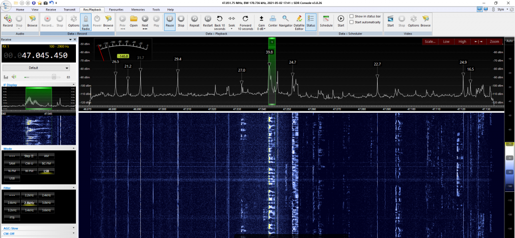
Bonus content
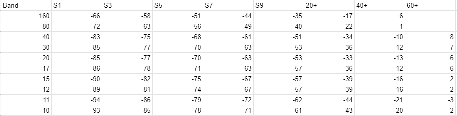
Here’s the sensitivity of this FT-840 as per a Marconi model 2018 signal generator with 1m of RG58. This remains pretty much unchanged with the hupRF board fitted.