Baofeng UV-5RA Carrier Detect/squelch open pin


For a project, I need to get a reliable Carrier Detect (or “my squelch is open, I am receiving”) signal out of a cheap and nasty Baofeng UV-5RA.

I’ve succeeded, and have done so by pulling together a few people’s work from around the web. I thought I’d pull it all together here.

This guy has done basically the same thing, using a Baofeng BF-888. Basically you take advantage of the fact the Baofeng powers on its audio amplifier only when the squelch is open. The radio applies 7.6V to pin 2 of the TDA2282 amplifier chip just under the LCD when the squelch is open. (Pin 4 is ground.) Take a feed from pin 2, to a 5k resistor, to the base (centre pin) of a BC547 NPN transistor. Ground the emitter (right pin, looking at the flat side). When the squelch opens, there is continuity between the collector (left pin) and the emitter – that’s your output.

Here’s the chip. Pin two is bottom row, second from the left. Pin 4 is bottom right. I ran very thin insulated wires around the edge of the board and up above the battery clip, behind the plastic cover.

credit: http://alaskareflector.org/zl1nc/UV-COS.html

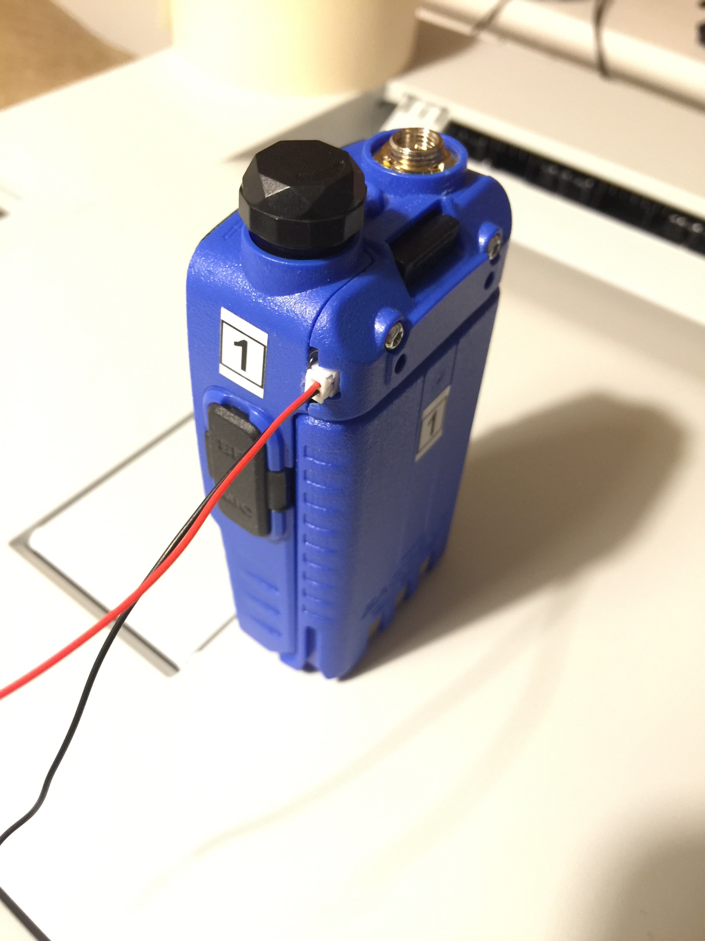
I’ve stuck a tiny socket up where the belt clip was:

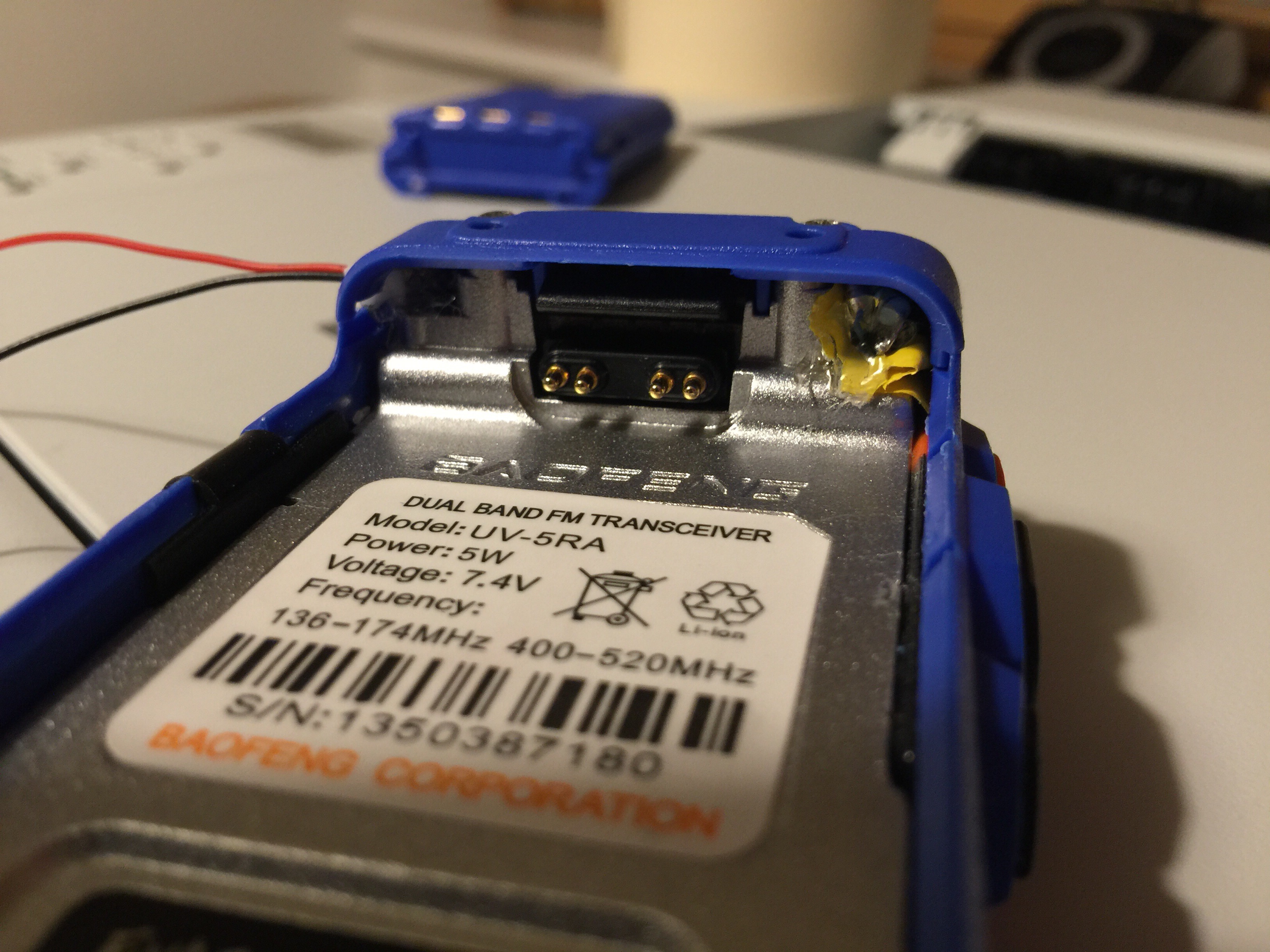
and I’ve shoved my transistor and resistor up behind the outer plastic cover above the battery on the right, dead bug style, hot glued on top of some insulating tape. Quite a bodge, but with some Dremel trimming of the case, it’s all held together fine by the top cover screws.

Multimeter reads continuity between the two output wires (red wire=collector, black wire=emitter) whenever the squelch is open, and open circuit when no signal is being received. Current should flow from the red wire to the black wire in any downstream interface.

Arduino Mobilinkd breadboard KISS TNC

Partly working… documenting my work so far towards a truly inexpensive, standalone, reliable APRS tracker.

I’ve moved away from the Pi and back over to microcontrollers. This is based on practical experience using the Pi at an event. Too much complexity / unknowns. The Pi worked okay, but could have been better.

So this below is based on http://www.mobilinkd.com/2014/09/11/arduino-kiss-tnc/
Which in turn seems to be based on https://sites.google.com/site/ki4mcw/Home/arduino-tnc

There’s actually a bit on KI4MCW’s page about how deaf the ADC design below is, might be worth looking at his improvements which don’t seem to have made it into the Mobilinkd hacking page.

Others doing the same:

So, here’s what is working so far:

  • Arduino Pro mini 5V clone @ approx £3
  • USB – 5V TTL serial cable
  • Baofeng / Wouxun / probably anything with 3.5+2.5mm TRS connector
  • For PTT:
    • 1k resistor
    • BC547B
    • 5V relay
    • diode
  • For TX audio:
    • 100k preset
    • 100nF / 0.1uF capacitor
  • For RX audio:
    • 2x 10k resistors
    • 10nF capacitor

Download firmware file from here or here

WinAVR from here or here

avrdude -c arduino -p m328p -P COM3 -b 57600 -U mobilinkd-473-arduino.hex

Grab MobilinkdTncConfig-0.6.1-win32.msi from this page

Ignore the stuff about Bluetooth, fire it up, set delay to 80 (800ms – these radios are properly rubbish), expect no confirmation (there is no save button – the author says (and I have checked) that changes are saved into EEPROM as you click in the UI). Check transmit using 1200Hz tone + Execute button.

Fire up aprsisce/32 or similar

APRSISCE/32 wants a Simply(KISS) port set up, 38400 baud, 8-N-1, and sometimes wants you to disable and re-enable the port before it works. Sometimes have to reset the Arduino too.

Turn the radio volume up quite high.

I plan to use a second Arduino, running a GPS, to push APRS frames in to this unit over serial.

Even better, mod this firmware to talk to a GPS over serial, then format and send its own APRS frames.

Circuit:

(EDIT: the RX circuit above, marked as unverified, is now verified working.)

(Another edit: for better PTT reliability, change the transistor connections as follows:

Collector to relay coil and diode anode
Relay coil and diode cathode to +5V
Emitter to ground
Relay contacts across Baofeng PTT (bare wire / 3.5mm sleeve) and Baofeng ground (blue / 2.5mm sleeve)) – need to update the text below.

Connections, taken down from working (TX, RX and PTT) breadboard:

  1. Headset red -> 100nF cap
  2. cap -> one side of 100k pot
  3. mid pot -> D6
  4. other side of pot -> gnd
  5. Headset blue -> gnd
  6. Headset bare -> BC547B emitter
  7. BC547B base -> 1k resistor
  8. resistor -> D10
  9. BC547B collector -> gnd
  10. Arduino GND -> gnd
  11. Arduino VCC -> vcc
  12. Headset green -> 10nF cap
  13. potential divider: gnd -> 10k resistor -> 10k resistor -> VCC
  14. cap -> mid of potential divider (2.5v)
  15. mid of potential divider -> A10

Baofeng pin assignments are here.

Code.

Baofeng / Wouxun common headset wire colours / assignments / PTT control

Green  2.5mm tip     rx audio +
 Blue  2.5mm sleeve  rx audio gnd,  ptt GND, rig gnd
 Bare  3.5mm sleeve  tx audio gnd,  ptt +V, NB NOT rig ground
  Red  3.5mm ring    tx audio +

To key the PTT, current must be able to flow from Bare (3.5mm sleeve) to Blue (2.5mm sleeve).

That is, either short Bare and Blue (sleeve to sleeve), or a current should be able to flow from Bare (3.5mm sleeve) to NPN transistor collector, to emittor, to Blue (2.5mm sleeve). An NPN transistor conducts from collector to emitter when a voltage is applied between base (+v) and collector (gnd)) – 5V + 1k resistor.

In other words:
The radio puts 3.3V down the Bare (3.5mm sleeve) conductor.
To key up, this must be shorted to the Blue (2.5mm sleeve) conductor.

RX audio is present between Green (2.5mm tip) and Blue (2.5mm sleeve)

TX audio should be pushed in to Red (3.5mm ring) and Bare (3.5mm sleeve)