Every FM data mode in pdn-soundmodem, the OFDM-FM floor at +5.8 dB carrier-to-noise included, stops at the same wall: the limiter-discriminator’s threshold. This project asks what sits under it. The answer, measured through the FM link model rather than on air: one slow audio-tone MFSK waveform into a Tait TM8100’s T13 decodes LDPC-coded frames 8 of 8 at -20 dB CNR from an SDR on the IF at 15 bit/s, 8 of 8 at -22 dB at 7.5 bit/s, and 7 of 8 at -18 dB from the R1 discriminator tap through a CM108 once the interface’s AC coupling is undone. That is 24 to 28 dB below the best FM floor today, and within about 3 dB of FT8’s efficiency per bit, through an FM transmitter.
The station assumed throughout is the one pdn-soundmodem is built around: a Tait TM8100 tapped at R1 and T13 through a CM108 interface, or the same radio with an SDR on its IF. Nothing has been on air yet. The short version is the blog post; this page has the detail.
- Design record with every table: docs/dev/plans/low-snr-fm.md in pdn-soundmodem
- The probe behind the numbers: prototypes/lowsnr-fm
- The IF tap added to the channel model: M0LTE.FmChannel,
ApplyToIf - Both on branch
claude/low-snr-fm-packet-modes-xnscal, not yet merged
Conventions
Every figure is carrier-to-noise ratio in the receiver’s IF bandwidth, which is where an FM threshold is defined and the only convention the FM link model uses. It is not SNR in 3 kHz, and nothing here converts to it without running the link. The link model is M0LTE.FmChannel: it really frequency-modulates a carrier, adds complex noise at the stated ratio, filters at the IF, and takes the angle between successive samples as a limiter and discriminator would. The threshold, the clicks and the rising noise spectrum emerge from that rather than being asserted.
Where the state of the art sits
| FM mode | Net rate | 50 % knee |
|---|---|---|
| ofdm-fm BPSK 1/2 | 1076 bit/s | +5.8 dB, the lowest anywhere in pdn-soundmodem |
| ofdm-fm QPSK 1/2 | 1964 bit/s | +6.3 dB |
| afsk1200-il2p | 1200 bit/s | about +7.5 to +8 dB |
| fsk9600-il2p | 9600 bit/s | about +10.5 dB |
The three bottom OFDM-FM rungs sit within 0.5 dB of each other, and no rung has ever been measured below +4.3 dB because none decodes there. The SSB weak-signal modes do not meet a discriminator at all: FT8 decodes at -21 dB SNR in 2.5 kHz for 77 bits in 12.6 s. Fed through an FM radio as audio, FT8 does not carry that across, because the radio’s threshold sits in front of it.
What the discriminator does to a weak signal
Two things, both Rice’s 1963 click model and both checked against the link model.
Suppression. With the carrier offset d from the IF centre at a linear ratio cnr, the discriminator’s mean output is d (1 - exp(-cnr)). At 0 dB the signal comes out at 63 % of its amplitude, at -10 dB at 9.5 %, and the power falls as cnr squared from there.
Clicks. Each time carrier plus noise circles the origin the phase slips a whole turn and the discriminator emits an impulse of area 2 pi. Their rate is (B / sqrt 3) erfc(sqrt cnr): on a 9.75 kHz IF about 55 a second at +5 dB, 730 at 0, 2100 at -4 and 3000 at -10. Each is white in the audio, and below about +6 dB they outweigh the Gaussian noise by orders of magnitude.
So a detector working on the audio sees a signal shrunk by cnr squared under white noise whose power is the click rate. For a tone of deviation D over a symbol T the output SNR is about D squared T (1 - exp(-cnr)) squared / 2N: 12 dB at -4 dB with 2.5 kHz deviation and 100 ms symbols, -1 dB at -15. Doubling T buys 3 dB against a term falling 20 dB per 10 dB of ratio. The audio path bottoms out near -8 dB whatever waveform or code runs on it, because the signal was multiplied by cnr squared before the code saw it. OFDM-FM’s floor is 14 dB above that; the rest is not a modem question.
The idea: detect in the phase, where the clicks vanish
The clicks are exact turns. A receiver that integrates the discriminator output back into a phase and takes exp(j theta) has rebuilt the limiter’s output: a unit-amplitude copy of the IF signal in which each click is a full rotation that leaves the phase where it was. The classic loss for detecting a weak signal after a hard limiter is pi/4, about 1 dB, with no threshold anywhere. The suppression is gone because it was never in the phase; it was the clicks’ asymmetry, and the clicks have been folded away.
flowchart LR
    TX["Audio tone MFSK<br/>into T13"] --> FM["FM transmitter"]
    FM --> CH["Carrier + noise<br/>at the stated CNR"]
    CH --> IF["IF filter"]
    IF --> SDR["S: SDR on the IF<br/>sideband detector on I/Q"]
    IF --> LIM["Limiter and<br/>discriminator"]
    LIM --> AUD["Audio out of R1"]
    AUD --> A["A: tone energy<br/>in the audio"]
    AUD --> INT["Integrate back<br/>to a phase, exp(j theta)"]
    INT --> P["P: sideband detector<br/>on the rebuilt phase"]
One waveform, three receivers, all run on every burst:
- A, audio. Energy at each tone in the discriminator audio, per symbol. What feeding FT8 to an FM radio does.
- P, phase. The discriminator audio integrated to a phase, exp(j theta), then the energy of the sideband pattern each tone produces (lines at plus and minus one and two times the tone), with a search over a common frequency offset for the burst.
- S, SDR. The same sideband receiver on the IF complex envelope, from the
ApplyToIftap added to the channel model for this.
The waveform: 8-ary FSK on audio tones at 1200 to 1270 Hz, 10 Hz apart, 100 ms per symbol, continuous phase, unit amplitude, at 2500 Hz peak deviation, so the modulation index is about 2 and the RF spectrum is the carrier plus sidebands at one and two times the tone. A single tone at full deviation is the friendliest thing a limiter can be given. Timing is a genie’s in all three receivers, so these are detection floors, not acquisition floors.
The floors, measured
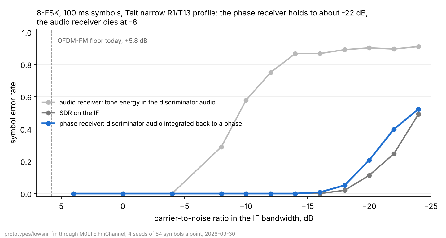
The audio receiver dies between -6 and -10 dB, where the cnr-squared arithmetic says it must, already 14 dB below the OFDM-FM floor. The phase receiver and the SDR stay within a decibel of each other all the way down, which is the pi/4 result holding through a real IF filter and a real audio low-pass. The SDR’s numbers are what theory gives an orthogonal 8-FSK detector at this rate: at -20 dB the energy per symbol over the noise density is 9.9 dB, of which the four sideband lines carry 92 % and pay about 1.5 dB for being four lines rather than one. A 250 Hz carrier error on the SDR path was found to 0.2 Hz by the burst-level search and cost nothing measurable.
Coded frames
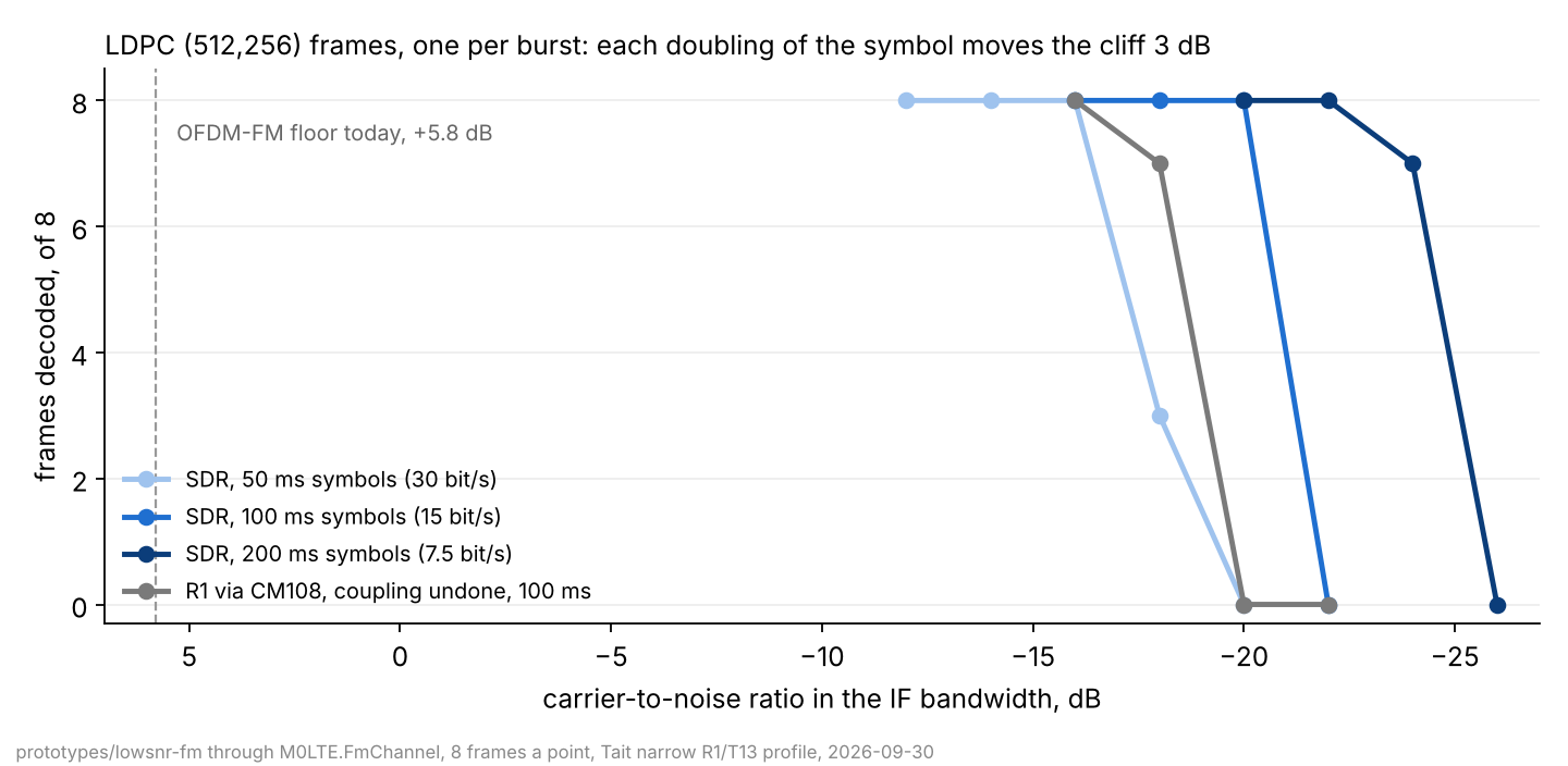
One LDPC codeword per burst, codec2’s H_256_512_4 from M0LTE.FecLdpc as OFDM-FM already uses it: 256 payload bits, 512 on air, 171 symbols. Bit LLRs are max-log over the tone energies, normalised to a mean magnitude of 2.5. Eight frames a point.
| Symbol | Net rate | CNR dB | Audio | Phase, DC coupled | Phase, 70 Hz coupling undone | SDR |
|---|---|---|---|---|---|---|
| 50 ms | 30 bit/s | -16 | 0 | 8 | 8 | |
| 50 ms | 30 bit/s | -18 | 0 | 0 | 3 | |
| 100 ms | 15 bit/s | -16 | 0 | 8 | 8 | 8 |
| 100 ms | 15 bit/s | -18 | 0 | 8 | 7 | 8 |
| 100 ms | 15 bit/s | -20 | 0 | 4 | 0 | 8 |
| 100 ms | 15 bit/s | -22 | 0 | 0 | 0 | 0 |
| 200 ms | 7.5 bit/s | -22 | 0 | 8 | 8 | |
| 200 ms | 7.5 bit/s | -24 | 0 | 1 | 7 | |
| 200 ms | 7.5 bit/s | -26 | 0 | 0 | 0 |
Each doubling of the symbol moves the SDR’s cliff by the 3 dB it should, so the rate is a dial: 30 bit/s at -16, 15 at -20, 7.5 at -22, and nothing stops 3.75 at -25 except the oscillators. With the SDR’s carrier 250 Hz off the 100 ms rows are identical. For the record, a microphone-and-speaker path gets the audio receiver and 8 of 8 at -6 dB, 0 at -8; it is not what this is designed for.
The CM108 coupling finding
The phase receiver needs the discriminator output DC-coupled, and the reason is a number worth keeping. Below threshold the phase is a random walk: N clicks a second, each a whole turn. Its frequency therefore has spectral density N right down to DC, and a high-pass at corner f_c removes N times f_c of it, leaving a frequency error that wanders with an rms of sqrt(N f_c) hertz. At -4 dB and a 70 Hz corner, which is where the interface notes put a CM108 on a flat R1 tap, that is 380 Hz of wander against tones 10 Hz apart. At a 1 Hz corner it is still 45 Hz.
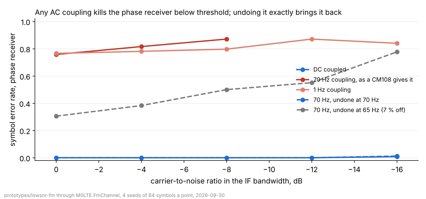
A bigger capacitor does not fix it, and tracking the wander symbol by symbol does not fix it, because at any corner the wander within one symbol is already too fast. What fixes it is undoing the coupling exactly: a one-pole high-pass has an exact inverse bar its DC, and with the inverse at the true corner and its integrator leaking at 0.005 Hz, the phase receiver is back on top of the SDR. The corner has to be known to about 1 to 2 %: 69 and 71 Hz against a true 70 both hold to -12 dB, 65 does not. The interface notes say the corner is not one component and that a single pole at 90 Hz and four poles at 35 Hz fit the same fifteen points, so the inverse has to be found rather than looked up: a search over corner and pole count that maximises the sideband receiver’s own metric on a burst above threshold, once per station. The SDR on the IF has nothing to undo, which is the strongest argument for the IF mod.
What it means at the antenna
On the model’s Tait narrow profile the noise in the 9.75 kHz IF at a 9 dB noise figure is -125 dBm, and the radio’s published 12 dB SINAD point of -121 dBm sits at about +4 to +5 dB CNR on that scale.
| CNR | At the antenna socket | |
|---|---|---|
| ofdm-fm BPSK 1/2, today’s floor | +5.8 dB | about -119 dBm |
| This waveform, R1 through a CM108 with the coupling undone, 15 bit/s | -18 dB | about -143 dBm |
| This waveform, SDR on the IF, 15 bit/s | -20 dB | about -145 dBm |
| This waveform, SDR on the IF, 7.5 bit/s | -22 dB | about -147 dBm |
Site noise moves every row together, not their spacing, so the decibels between rows are what carry. 26 dB is 20 times the distance in free space and about five times over a path losing 35 dB per decade. Per bit, the SDR floor of -20 dB in 9.75 kHz is -14 dB in 2.5 kHz; at 15 bit/s that is an Eb/N0 of about 8 dB, against FT8’s 5 dB at 6.1 bit/s. Most of the 3 dB is the four-line combining loss and non-coherent 8-FSK; a coherent phase-modulated version of the same idea would close it.
The design
Waveform. Slow non-coherent MFSK on audio tones at the modulation index that puts the energy in the first two sideband pairs (about 2: 1250 Hz at 2500 Hz deviation, 2500 Hz at 5 kHz on a 25 kHz channel). 8 tones, 10 Hz spacing, 100 ms symbols as the baseline; 50 ms at 20 Hz spacing where drift or flutter says so. Non-coherent by choice, as FT8, WSPR and datac14 chose, because a commercial VHF synthesiser’s phase is not something a 100 ms symbol can be asked to trust. Tones rather than a DC shift because T13 has a 3.7 Hz high-pass behind it; the tones cost about 1.5 dB and are what T13 can carry.
Two receivers, one transmitter. The transmitter is T13 in both cases.
- R1 into the CM108. The phase receiver with the coupling undone. Frames to -18 dB at 15 bit/s, provided the corner is calibrated to 1 to 2 %. That calibration is the one piece with no precedent.
- An SDR on the IF. The same sideband detector on complex baseband, the carrier search widened to about plus or minus 400 Hz for two radios at 1.5 ppm on 2 m. Frames to -20 dB at 15 bit/s and -22 at 7.5, nothing to calibrate, and the radio’s front end and IF filter still in front of the SDR’s ADC. Where the mod exists, build this first.
Framing. At 15 bit/s a plain AX.25 UI frame spends 144 bits, nearly ten seconds, on addresses, control and PID. Carry the IL2P header (104 bits, already in tree) or a station-table index once both ends have heard each other, one LDPC codeword per burst sized to the payload, the length signalled by which sync pattern opens the burst, CRC inside the codeword as datac does.
Sync. A Costas array of the tones at the start and end of the burst, searched in time and offset by the same zero-padded FFT the receiver already runs, as FT8 does; FT8’s experience is about 1 dB against a genie. Slot-timed operation on UTC boundaries removes most of the search and makes channel access deterministic.
Channel access. Nothing on the station can see a signal at -20 dB and the squelch is closed, so the only carrier sense is the mode’s own sync detector. A frequency of its own, slot-timed, with the node scheduling replies into slots: UI frames, beacons, short messages and mailbox polls, not connected mode.
Plan and gates
Every gate is a ladder through M0LTE.FmChannel, eight or more seeds a point, quoted as frames of N at a CNR. The model’s floors stay model numbers until C1 ties them to a radio.
- A1 Waveform and receivers. The three receivers as an
IModem. Exit: reproduces the symbol error chart with genie timing. - A2 Acquisition. Costas sync, time and offset search, per-symbol tracking. Exit: within 1 dB of the genie at the 50 % point; false decode rate on an hour of noise stated.
- A3 Framing. IL2P header or station table, codeword ladder, CRC, length signalling. Exit: a frame ladder per codeword size.
- B1 Levels at T13. Full legal deviation from T13’s 0.29 Vp-p per kHz; the receiver’s deviation scale calibrated from a burst above threshold.
- B2 R1 into the CM108. The coupling inverse and its blind calibration. Exit: through a modelled 70 Hz one-pole and a modelled four-pole at 35 Hz, frames to -18 dB. This gate decides whether the CM108 receiver exists.
- B3 SDR on the IF. Carrier and sample-clock offsets. Exit: frames to -20 dB at 15 bit/s and -22 at 7.5, at plus or minus 400 Hz.
- C1 A real ladder. The CNR axis on a real Tait: an attenuator between two radios, RSSI over CCDI as the independent axis. Exit: the -18 and -20 dB rows reproduced within 3 dB on hardware, the model re-pinned if not.
- C2 The tap and the SDR. The IF mod with an SDR, and R1 into a sound card B2 has calibrated. Exit: a frame off air at a level no other mode decodes at.
- D1 and D2. A slot-timed port on a node with UI frames, then header compression by station table.
Risks and open questions
- Oscillator drift. 10 Hz tones over a 17 s burst ask the two radios to hold to a few hertz relative to each other for that long. A TM8100 is specified to 1.5 ppm over temperature, 220 Hz at 145 MHz, but drift within a burst is thermal and slow, and nothing has measured it. The 50 ms symbol is the fallback.
- Flutter and multipath. Nothing has been run with flutter set. The fixed stations this is for do not flutter much, but it needs a row in every ladder.
- False decodes. At -20 dB the receiver decides among eight hypotheses on energies that are mostly noise. LDPC convergence and the CRC are the backstop, as in datac; the rate on pure noise has to be stated.
- The coupling calibration. The only gate whose method is untested. If a real dongle’s coupling is not a small number of poles, the CM108 receiver falls back to a DC-coupled ADC, which is a hardware project.
- Level. The phase receiver needs the discriminator output in known units; the sideband pattern is only mildly sensitive to the scale, but it is another number to calibrate.
- Air time. 17 s bursts on a shared frequency are not courteous. A frequency of its own is a requirement.
Two decoder findings
Written down so nobody meets them twice. M0LTE.FecLdpc’s sum-product decoder only converges on LLRs in a narrow magnitude window: fed synthetic LLRs of uniform magnitude with 2 % of signs flipped it decodes 50 of 50 at magnitude 2.5, 42 of 50 at 6, and 0 of 50 at 1 or 0.2, where it runs to its iteration limit. Normalise to a mean magnitude of 2.5, which is what OFDM-FM’s coding layer settled on. And the codec keeps state, so one instance shared across parallel bursts corrupts them; that looked like a channel result for an hour.