Every FM data mode in pdn-soundmodem stops at the same place. AFSK 1200 needs about +8 dB carrier-to-noise in the receiver’s IF, 9600 baud about +10.5, and the best of them, OFDM-FM at 1 kbit/s, +5.8 dB. Below that the radio’s discriminator stops handing up a signal and starts handing up clicks, and no amount of coding on the audio gets you far past it. So a station whose path is 20 dB short of that is simply not on the network.
I spent a session on what sits under that wall, with the FM link model rather than a radio, and the answer is more than I expected. The full write-up is the project page; this is the short version.
Why FM modes fall off a cliff
An FM receiver’s limiter and discriminator do two things to a weak signal, and both are old results (Rice, 1963) that the link model reproduces rather than assumes. First, the signal is suppressed: the discriminator’s output shrinks by (1 - exp(-cnr)), which is 63 % at 0 dB and under 10 % at -10 dB, so the signal power falls as the square of the ratio. Second, every time carrier plus noise circles the origin the phase slips a whole turn and out comes a click, an impulse of area 2 pi. At 0 dB on a 12.5 kHz channel that is about 700 clicks a second; at -4 dB, 2000.
Put those together and anything that decodes the audio as audio bottoms out near -8 dB, whatever the waveform and whatever the code, because the signal was multiplied by cnr squared before the code saw it. Slower symbols buy 3 dB a doubling against a term that is falling 20 dB per 10 dB of ratio. That is the wall, and it is not a modem problem.
The trick
The clicks are exact turns. If you integrate the discriminator’s output back into a phase and take exp(j theta), each click becomes a full rotation that leaves the phase where it was. You have rebuilt the limiter’s output, a unit-amplitude copy of the IF signal, and the known cost of detecting a weak signal after a hard limiter is about 1 dB, with no threshold anywhere. The suppression was never in the phase; it was the clicks’ asymmetry, and the clicks are gone.
So the waveform is the simplest thing an FM radio can carry, a single audio tone at full deviation, eight tones 10 Hz apart as 8-FSK at 100 ms a symbol, and there are three receivers for it:
- Audio: the energy at each tone in the discriminator audio. What feeding FT8 to an FM radio does.
- Phase: the audio integrated back to a phase, then the tone’s sideband pattern detected on the unit circle.
- SDR: the same sideband detector on the IF itself, from a tap added to the channel model for this.
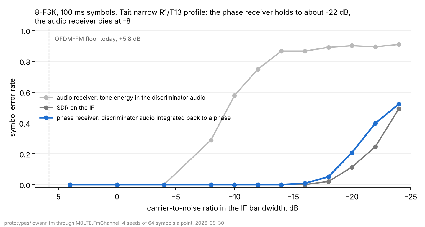
The audio receiver dies at -8 dB, as the arithmetic says. The phase receiver and the SDR hold to about -22 dB, within a decibel of each other all the way down, through a real IF filter and a real audio low-pass. With an LDPC code on top, one codeword a burst at 15 bit/s, the SDR decodes 8 of 8 frames at -20 dB and the phase receiver 8 of 8 at -18. Double the symbol and the cliff moves 3 dB: 8 of 8 at -22 dB at 7.5 bit/s.
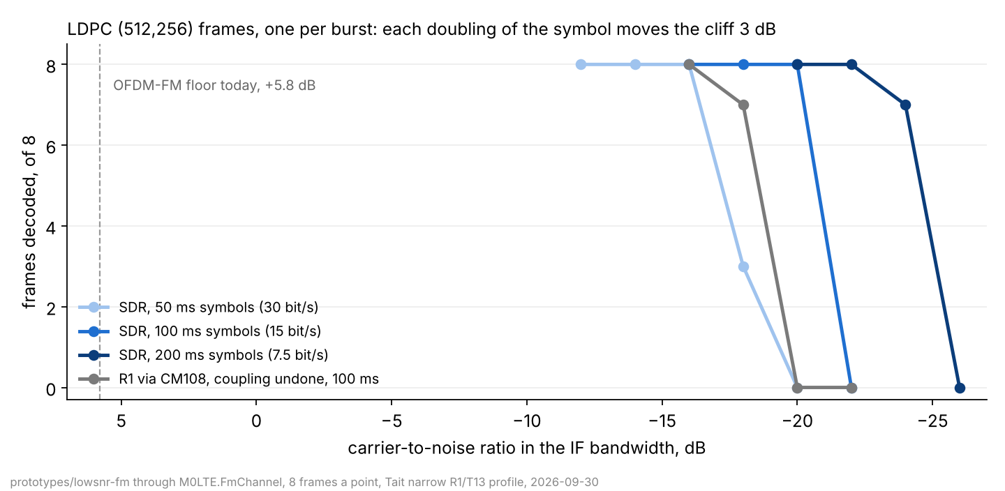
Against today’s floor of +5.8 dB that is 24 to 28 dB, which is 20 times the distance in free space. Per bit it is within about 3 dB of FT8, through an FM transmitter.
The catch, and it is a number
The phase receiver needs the discriminator output DC-coupled, and a sound card is not. Below threshold the phase is a random walk of clicks, so its frequency has energy right down to DC, and any high-pass at a corner f_c leaves a frequency error wandering by about sqrt(N f_c) hertz. With 2000 clicks a second and the 70 Hz corner a CM108 interface gives on a flat R1 tap, that is 380 Hz of wander against tones 10 Hz apart. A bigger capacitor does not help: a 1 Hz corner still leaves 45 Hz.
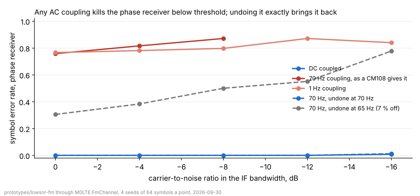
What does help is undoing the coupling exactly in software, which a one-pole high-pass allows, bar its DC. With the inverse at the true corner the phase receiver is back on top of the SDR. The corner has to be right to 1 or 2 %, and a real interface’s corner is not one component, so the receiver will have to find it itself from a burst above threshold, once per station. An SDR on the IF has nothing to undo, which is the best argument I have for the IF tap.
What exists
- The design record, with every table, the design and a gated plan from a modem with real acquisition through a real-radio ladder to a slot-timed port on a node.
- The probe that produced the numbers: three receivers, the coupling model and its inverse, offset search and tracking, and the LDPC frame mode.
- An IF tap on M0LTE.FmChannel, so an SDR receiver can be measured with the same physics as a discriminator one.
Nothing has been on air. Everything above is the model’s number until a real Tait ladder ties it to hardware, and that ladder is the first gate.